Guitar Rewiring
We will NOT be discussing the actual winding or rewinding of pickups. That
is much too difficult to accomplish. Instead, we will talk about the
circuitry inside of a guitar. By making some very minor
modifications (particularly switching), a guitar's sound can be changed
dramatically.
|
| |
|
Volume and Tone Controls
Although we will be primarily discussing switching, let us first
show 2 wiring diagrams of a guitar's volume and tone controls.
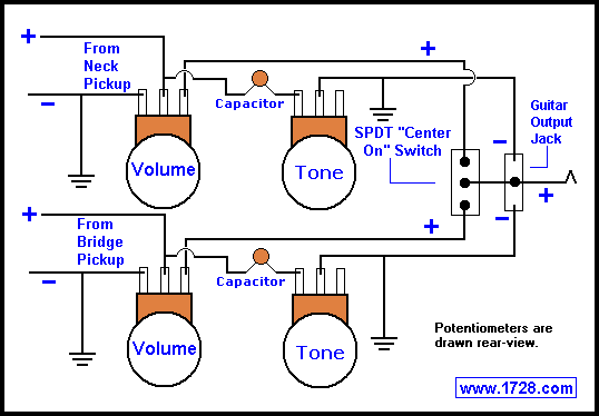
NOTE: In these diagrams, the volume and tone controls are viewed from the rear.
The volume and tone controls are variable resistors, also known as
potentiometers (or "pots" for short). In electric guitars, the values
for either of these usually is about 250K to 1 megohm. The capacitor
in the circuit is for the tone control and these values usually are
from .02 to .047 mfd (short for microfarad).
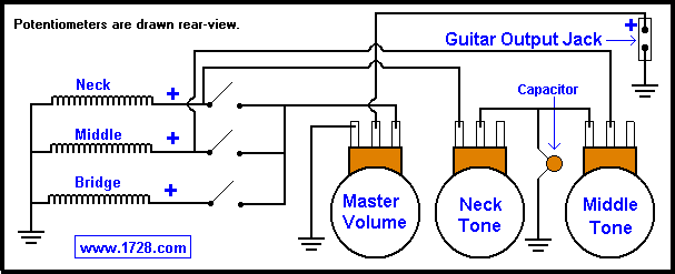
The top diagram shows the way in which Fender wires its volume control.
(This is the best way to wire a master volume control).
Fender generally uses 250K "pots" and .02 mfd capacitors.
The bottom diagram shows the wiring that Gibson uses for its volume controls.
This is the best wiring method to use when you are using a volume and tone control for each pickup.
When both pickups are active, this circuit allows one pickup to remain active when one volume control is turned all the way down.
Gibson generally uses 500K "pots", .047 mfd capacitors for the
neck tone and .02 mfd capacitors for the bridge tone control.
SPDT Switch
Rewiring a guitar can dramatically change its sound. If you are
unsure of basic switch terminology, please go to this tutorial first:
Switches
 Pictured above are two Single Pole Double Throw (SPDT) switch diagrams.
ALL SPDT switches
have their common terminal in the middle and they ALL function
as shown in the above diagram.
In position 'A', the center terminal connects to the top terminal.
In position 'B', the center terminal connects to the bottom terminal.
 There are 2 special
cases of SPDT switches that have the functions as shown in diagrams
A & B plus they have a third position whereby the
common terminal connects to both outer terminals (diagram C)
OR the common terminal connects to neither terminal (D).
There are 2 special
cases of SPDT switches that have the functions as shown in diagrams
A & B plus they have a third position whereby the
common terminal connects to both outer terminals (diagram C)
OR the common terminal connects to neither terminal (D).
These are called the "SPDT center on switch" (C)
and the "SPDT center off switch"
(D).
These switches are called center on or off because this third
switch position is located in between 'A' and 'B'. For example, if
this were a toggle switch, this middle or 'center' position would
occur when the switch lever was straight up.
Even though these switches have 3 positions, they are still considered
double throw because another 'throw' implies a connection to yet another
terminal and as we can see, diagrams C & D have the same number of terminals
as A & B.
The best example of an "SPDT center on switch" is the pickup switch
used on guitars with 2 pickups (the Gibson Les Paul™, the Gibson SG™,
etc).
Pictured above is the pickup switching diagram for a 2 pickup guitar.
On the right is a single pole double throw switch (SPDT) center on
switch.
The middle connection is the 'common' terminal and this is where you
connect the output wire. (This is the wire that goes to the volume
control or may go directly to the output jack).
Basically, when the switch lever is in one position, the neck pickup is
active and in the other position, the bridge position is active.
In the 'middle' switch position, both pickups will be 'on'.
This SPDT center on switching arrangement is extremely
common on 2 pickup guitars.
DPDT Switch
 ALL DPDT switches have their center terminals as the common terminals
and they ALL work like diagrams A and B.
ALL DPDT switches have their center terminals as the common terminals
and they ALL work like diagrams A and B.
In position 'A', the
common terminals connect to the top terminals and in position 'B',
they connect to the bottom terminals.
 There are 2 special cases of DPDT switches, pictured in diagrams 'C' and 'D'.
Diagram C shows the middle
position of the more common type of "DPDT center-on switch". Here the
common terminals connect to the top and bottom terminals simultaneously.
This is the typical DPDT center on switch that you would find at Radio Shack and
most electronic parts suppliers.
Diagram D shows the middle
position of a highly specialized type of DPDT center-on switch.
Here the common terminals connect as shown in the diagram.
Some refer to this as a "DPDT on/on/on switch" but as you can
see, the switch in Diagram C could be referred to in the same way.
The biggest use of this switch is for wiring humbuckers in
series / coil-cut / parallel. This is the only way you can get
all 3 options in one switch.
Now that you know about switches, let's talk very briefly
about:
Guitar Pickups
If you read about relays, you will learn
that an electromagnet is a chunk of metal (usually iron), wrapped
with a great deal of wire. When an electrical current flows though the
wire, a magnetic field is produced.
A guitar pickup
is the reverse of this whereby we start with a magnet and wrap a huge amount
of wire around it (thousands of turns, usually). When guitar strings
(or any metal) moves through the magnetic field, an electrical current is produced.
|
| |
|
In the next section, we'll discuss various switching arrangements of a guitar's pickups
so that a great many tones can be produced.
Just remember that:
• Any modification you do to your guitar will void the warranty.
• Some of these modifications will change the appearance of your guitar.
• If you are not sure of your electronic skills you may actually do
damage to your guitar for which we will not be responsible.
• Similarly, you may alter the guitar in such a manner that it becomes
unsafe electrically in which case you could be harmed. Again,
we will not be responsible for any injuries.
3 Single Coils Wired In Parallel

This diagram shows 3 single coils wired in parallel, allowing seven tone
choices. The typical 3 single coil guitar contains a 5 way rotary
switch which allows you to get 5 sounds - each single coil; neck and middle
in parallel and middle and bridge in parallel. This modification will
give you 2 more sounds - all 3 pickups in parallel and Neck and Bridge
in parallel.
3 Single Coils Wired In Series
This diagram shows 3 single coils wired in series, allowing seven tone
choices. Note that the switches
are wired such that they shunt (or short-circuit) the coils so that they
get bypassed.
With this modification, you will not get any parallel sounds
which are so typical of the "Fender sound". (For example, "Sultans
of Swing" is played with the middle and bridge pickups in parallel).
The pickups in series gives you a fuller sound with much higher output,
which is good for distortion. If you want a more versatile modification,
go to the Wolf Wire™ Modification which will give
you series choices, parallel, single coil, and out of phase options.
Humbuckers
Humbucking pickups are essentially 2 single coils right next to each other in one
"package". If you want to know how this pickup cancels the hum, click
here.
Since there are 2 coils, you can have up to 4 wires with which to
work, providing you with a great many tone options. Almost all independent pickup
companies manufacture humbuckers with 4 conductor cable.
Stock guitar humbuckers rarely have 4 wires coming out of them but
sometimes it is possible to convert 2 wire humbuckers to 4 wire types.
This is an exacting procedure with little room for error but the tone rewards can
be well worth the effort. If you really want to
give this a try, then click here.
|
| |
|
Pickup wire colors vary for each manufacturer.
Two of the most popular manufacturers are Dimarzio and Seymour Duncan
and their wiring codes are:
Additional pickup wire colors can be found here.
The traditional method for wiring a humbucker is to wire the coils in series:
 If you wanted to wire a 4 conductor Dimarzio or Seymour Duncan in this
way, just look at the diagram. Solder the 2 "middle wires" together,
tape the connection, then solder the outer wires to the output. Be very
careful when working with 4 conductor wiring. The colors and polarity are
very important. You could easily make a mistake and wire an
"out-of-phase" arrangement which would have low output, a squawky,
thin sound AND the humbucker would NOT be hum canceling.
If you wanted to wire a 4 conductor Dimarzio or Seymour Duncan in this
way, just look at the diagram. Solder the 2 "middle wires" together,
tape the connection, then solder the outer wires to the output. Be very
careful when working with 4 conductor wiring. The colors and polarity are
very important. You could easily make a mistake and wire an
"out-of-phase" arrangement which would have low output, a squawky,
thin sound AND the humbucker would NOT be hum canceling.
Another humbucker advantage is that the 2 coils
make it have a much higher output than a single coil pickup. This gives them
a much fuller sound and produces a "fat" warm overdriven sound.
Sometimes though, this extra output might be a little too
"muddy" than you'd want it.
Wiring the coils in parallel will produce a brighter tone (with
somewhat less volume than series), but will still be humbucking.
 Again, the humbucker could be permanently wired in the manner shown in the above diagram. However, if you permanently wire the humbucker for series or parallel, you are seriously limiting your tone options.
Rather than settling on just one permanent wiring, a very good choice is to put a series/parallel switch on a humbucker.
 The black line you see in the diagram is a "jumper" wire connecting the upper left switch terminal to the upper right terminal. This wire is necessary to connect the 2 "middle wires" so that the humbucker can be connected in series.
The kind of switch you'll need is a Double Pole Double Throw with no center position. (See diagrams A & B in the above DPDT switch section).
In this way you can switch tones right in the middle of a song and you can go from a bright tone to a fuller, louder tone that is quite suitable for overdriving an amplifier.
Yet another tone option for humbuckers is the
coil-cut switch.
Here you get a very bright sound but the output will be less than if it
were wired in series and you no longer have hum canceling.
Since you are using just
one half of the humbucker, "coil-cut" sounds best when using a high
output pickup (DiMarzio "X2N", DiMarzio "Distortion", Seymour Duncan "Invader",
Seymour Duncan "Distortion", etc). A coil cut switch is
relatively easy to wire up
and it is just a matter of connecting one end of an SPST switch to that
junction that was created for series wiring and connecting the other
end of the switch to ground. So, we now have another 2 tone humbucker arrangement that can easily be switched back and forth between 2 tone options.
To read more about coil cut switching, please click here.
Still, if you have a humbucker with 4 conductors, you might want to go all the way and wire it
for all 3 of the tone options we have discussed. The best way to do this
is with a special DPDT on/on/on switch (see Diagram D in the previous
section).
 This is a "neat" arrangement because you get the 3 best humbucker tone
options all in one switch. Still, you might have trouble finding this
type of switch OR you might not like having a 3 position toggle switch
because it is hard to switch to the middle coil cut position OR you'd
rather have a smooth parallel to series switching option.
This is a "neat" arrangement because you get the 3 best humbucker tone
options all in one switch. Still, you might have trouble finding this
type of switch OR you might not like having a 3 position toggle switch
because it is hard to switch to the middle coil cut position OR you'd
rather have a smooth parallel to series switching option.
If that is the case, use a standard DPDT Switch with NO middle
position (Diagram A or B) and use a separate SPST switch for the coil
cut option.
This arrangement does have all the advantages mentioned above. However it
has the disadvantages in that the coil-cut switch will only work when the
DPDT switch is set at the 'series' position and it may require another hole to be drilled in your guitar for that additional switch.
Phase Reversal Switch
For single coils OR humbuckers.
Another tone option for a guitarist is to put a pickup out of phase
with another pickup, producing a thin "inside-out" squawky kind
of sound. When 2 pickups are in phase, they work together and
reinforce each other. When they are out of phase the 2 pickups
are working against one another and the resulting sound is the
"leftovers" from these cancelations. The closer the 2 pickups are,
the greater the cancelations, the thinner the sound and the lesser
the volume. Therefore, the neck and bridge pickups out
of phase is the best choice for this type of sound.
In order to achieve this sound (and to go back to a regular sound), we
use a phase reversal switch (see above diagram). (For an explanation of how
this switch works, go to Basic Electricity
and scroll down to the 'Double Pole Double Throw' section).
It is important to state that you do not have to use
2 phase switches because reversing the leads of both pickups would
put them back in phase!!
Wiring the phase switch is fairly simple. Solder 2 wires in the
criss-cross manner shown in the diagram. In the guitar cavity,
unsolder the 2 bridge pickup leads; solder the phase switch "Out"
leads to the exact same spot where the pickup leads were;
solder the bridge pickup leads to the "From Pickup" terminals on the
phase switch. Mount the switch, close up the guitar and start enjoying
the new sound you just created!
Humbucking Pickup Out Of Phase With Itself
As stated previously, the closer 2 coils are to one another, the
greater the cancelations will be when they go "out of
phase". So, wiring a humbucker out of phase with itself is going to
produce a lot of cancelations, a huge reduction in volume and
a very thin sound. If that's not enough, the pickup will not
be humbucking either. Still there are some people that like this kind
of sound. The best way to put a humbucker out of phase with itself is
to wire the coils out of phase in series.
(see below)
Just to make sure we "cover all the bases", it is possible to wire a
humbucker
out of phase with itself in parallel. This
produces the thinnest, lowest output of all possible phasing
combinations. Still, for those that want to give this a try here is
the wiring diagram.
Other Guitar Rewiring Pages On This Site:
Return To Home Page
Copyright © 1999 -
1728 Software Systems
|
|