Copyright © 1999 -
1728 Software Systems
Basic Electricity
IMPORTANT !!! DO NOT use wall current !!!
ALL of these circuits can be built using batteries (dry cells) only !!!
If you have no experience with wiring OR if you want suggestions
on what supplies to buy, click here.
As is the case with the "Lincoln Cent Project",
electricity is another
good example of science being part of our everyday lives. Look
around you. Your television, your clock radio, the computer you are using
and many other electrical appliances are all utilizing
electrical power.
To explain things as briefly as possible, electricity is a flow of electrons.
Substances that allow electrons to flow freely are called
conductors
and those that don't are called
insulators.
E L E M E N T A R Y C I R C U I T S
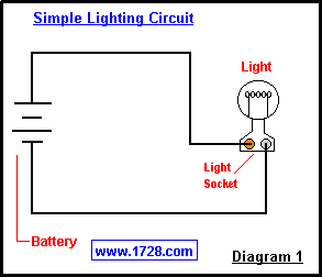 Diagram number 1 illustrates an
extremely simple circuit. The battery is represented by 4 horizontal lines.
Starting from the negative end (-) of the battery, electrons "circle"
through one wire, pass through the light bulb, pass through the other wire
and then
return to the battery (+), thereby completing the circuit. See? Quite simple. Diagram number 1 illustrates an
extremely simple circuit. The battery is represented by 4 horizontal lines.
Starting from the negative end (-) of the battery, electrons "circle"
through one wire, pass through the light bulb, pass through the other wire
and then
return to the battery (+), thereby completing the circuit. See? Quite simple.
This is all well and good but there are 2 drawbacks
to this circuit:
1) the light
always stays on and
2) the power is constantly
being used.
How can we turn the light bulb 'off'? Well, we could unscrew
the bulb from the socket but in the real world this is very inconvenient.
(Light bulbs are inside fixtures, on ceilings and so on).
Perhaps we could disconnect the power at the source. This too is very
inconvenient. You
would have to go down to your basement to shut the power off.
Or - much more
dangerous - you would have to disconnect the electrical supply wire
before it reaches the light socket.
Is there a safe way to interrupt the
electron flow without physically touching the wire? Sure. It is called a
SWITCH !!!
The inside of a typical household wall switch
has a strip of metal (B), making contact with point 'A', completing the circuit and
thereby conducting electricity to the light. This would obviously be the 'ON' position.
When the insulated lever is moved down to the 'OFF' position, it pushes the metal strip
away from point 'A', breaking the circuit and turning the light 'OFF'.
This type of switch (having a lever which "flips" it on and off) is called a
toggle switch.
Because of being well-insulated
and mounted in a box, household switches are a safe way
for turning electrical devices on and off.
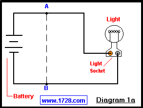
Now let's look at Diagram 1a and that dotted line going from point A to point B.
What would happen
if point A and point B were to touch OR if they were connected with a wire or
other conductor?
Well, the light bulb would turn 'off', the wires and the
battery would get very warm very fast and the electrons would simply travel
from the battery to point A to point B and then back to the battery.
Notice that
in this new circuit , the electrons are
traveling a path (or circuit) that is shorter than the original one.
Hence you have just learned what a "short circuit"
is and how its name is derived!
Short circuits are dangerous. They cause wires to heat, circuit breakers
to 'trip' and can even start fires.
S W I T C H E S
There are
many different types of switches: toggle, rotary, pushbutton,
"rocker", "pull-chain", slide, magnetic, mercury, timer, voice-activated,
"touch-sensitive", and many others. Heck, even the Clapper™ is another
type of switch !
The "knife switch" (rarely seen
nowadays) is the type that most easily demonstrates the functioning of a
switch. Old sci-fi movies ("Frankenstein (1931)" or
"Young Frankenstein (1974)", for example), made extensive use of these switches in the laboratory scenes.
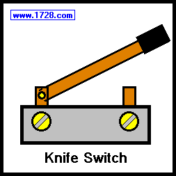
Today, use of knife switches has been
confined to 1) heavy-duty industrial applications and 2) demonstration
purposes - science projects for example. The knife switch has a metal lever,
insulated at the 'free end' that comes into contact with a metal 'slot'. Since
the electrical connections are exposed, knife switches are never seen in
household wiring.
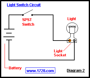 Referring to Diagram 2, the wiring
is very similar to Diagram 1 except a switch has been added. Compare this
to the Typical Household Light Switch diagram. Pretty much the same principle at work
wouldn't you say? This type of switch is a Single Pole Single
Throw (or SPST). This means that it controls one wire (pole)
and it makes 1 connection
(a throw). Yes, this is an on/off switch, but a 'throw' only counts when a
connection is made. 'Off' is not considered a 'throw'. Also notice that only
1 wire has to be switched. (Following the circuit from one end of the
battery to the other you can see why this is so). Referring to Diagram 2, the wiring
is very similar to Diagram 1 except a switch has been added. Compare this
to the Typical Household Light Switch diagram. Pretty much the same principle at work
wouldn't you say? This type of switch is a Single Pole Single
Throw (or SPST). This means that it controls one wire (pole)
and it makes 1 connection
(a throw). Yes, this is an on/off switch, but a 'throw' only counts when a
connection is made. 'Off' is not considered a 'throw'. Also notice that only
1 wire has to be switched. (Following the circuit from one end of the
battery to the other you can see why this is so).
As it is, this circuit
alone could be your science project. A variation could be substituting a
push-button switch and putting a 'buzzer' or 'doorbell' where the light is. Now you have a
good demonstration of how a doorbell is wired. Pushbutton switches are
usually "momentary on".
That is to say the connection is made only when
you press the button. There are "momentary off"
pushbutton switches, but
using one in a doorbell circuit would mean the bell would be constantly on
until someone pressed the button. Impractical don't you think?
(The comedian Tim Conway joked that his father wired a doorbell in just this
way. When there was silence someone would say "Hey somebody's at the door").
A practical use of the momentary off
switch is the "mute button" on
your telephone. If a momentary on switch were used, it would be very
annoying to press the button constantly as you talked and released it only
for muting. This shows how each type of switch has its specific applications.
 The above diagram shows an
interesting variation of doorbell wiring. The 2 doorbell buttons do not
have to be right next to each other. One button could be at a front door and
the other at a side door. If you follow the circuit, you can see that
pressing either button will cause the doorbell to ring. The 2 switches
are said to be wired in parallel.
The above diagram shows an
interesting variation of doorbell wiring. The 2 doorbell buttons do not
have to be right next to each other. One button could be at a front door and
the other at a side door. If you follow the circuit, you can see that
pressing either button will cause the doorbell to ring. The 2 switches
are said to be wired in parallel.
 The burglar alarm circuit at left employs magnetic switches. These switches and their
associated magnets are generally mounted on doors and windows. Notice that
Switch 1 and Switch 2 are wired in series.
Both switches must be closed in order for the circuit to be complete and
for the bulb to light. (This would indicate the 'armed' status of this
burglar alarm.)
Magnetic switches come in 2 varieties - "Normally Closed" and "Normally Open".
These 2 terms describe the state of the switch
when it is NOT being controlled by the magnet. The switches in this diagram
are the "Normally Open" type and because the magnets are far
enough away, the switches are in the 'open' state. If the magnets were brought
closer, the bulb would go on and the circuit would be "armed". At this point,
moving either magnet would make the bulb go out and the alarm would be triggered.
(For the sake of simplicity, the activated alarm circuit has not been drawn).
An important point to note is that cutting the wires at any point
would also make the bulb go out and trip the alarm.
The burglar alarm circuit at left employs magnetic switches. These switches and their
associated magnets are generally mounted on doors and windows. Notice that
Switch 1 and Switch 2 are wired in series.
Both switches must be closed in order for the circuit to be complete and
for the bulb to light. (This would indicate the 'armed' status of this
burglar alarm.)
Magnetic switches come in 2 varieties - "Normally Closed" and "Normally Open".
These 2 terms describe the state of the switch
when it is NOT being controlled by the magnet. The switches in this diagram
are the "Normally Open" type and because the magnets are far
enough away, the switches are in the 'open' state. If the magnets were brought
closer, the bulb would go on and the circuit would be "armed". At this point,
moving either magnet would make the bulb go out and the alarm would be triggered.
(For the sake of simplicity, the activated alarm circuit has not been drawn).
An important point to note is that cutting the wires at any point
would also make the bulb go out and trip the alarm.
The next type of switch (no diagram) is the
Double Pole Single Throw (DPST). These switches are used when there are
2 'live' lines to switch but can only turn on or off (single throw). These
switches are not used much and are usually found in 240 volt applications.
Single Pole Double Throw Switches
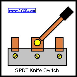
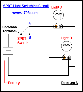 Diagram 3 makes use of the Single Pole
Double Throw Switch. The common terminal is the middle terminal in the
SPDT Knife Switch or if you are using a household switch, it would be the
brass colored terminal. (the other 2 would be silver colored). This circuit
clearly demonstrates what happens when the SPDT switch is moved back and
forth. Light A goes on and B goes off, B goes on and A goes off and so forth.
You can see that this popular switch would have many practical applications:
the transmit/receive button on a "2-way" radio, the "high/low beam" switch for
your car headlights, the pulse/tone dialing switch on your telephone, and
so on. Diagram 3 makes use of the Single Pole
Double Throw Switch. The common terminal is the middle terminal in the
SPDT Knife Switch or if you are using a household switch, it would be the
brass colored terminal. (the other 2 would be silver colored). This circuit
clearly demonstrates what happens when the SPDT switch is moved back and
forth. Light A goes on and B goes off, B goes on and A goes off and so forth.
You can see that this popular switch would have many practical applications:
the transmit/receive button on a "2-way" radio, the "high/low beam" switch for
your car headlights, the pulse/tone dialing switch on your telephone, and
so on.
If you are using the SPDT knife switch, you have a "center off" position,
which an ordinary wall switch would NOT have in which case you will need to
add an SPST switch for shutting this circuit off. (In electronics work,
many SPDT switches have a middle position in which the electricity is turned
off to BOTH circuits. It is an SPDT center off
switch. Also, some electronic SPDT switches have a "center on"
position. The best example of this type of switch is the "pickup" selector
on an electric guitar which can choose the rhythm, treble or both pickups
for 3 varieties of sounds).
Diagram 4 (below) depicts what is probably the most
common use for the SPDT switch - the
3 way light switching
circuit. Electricians
incorrectly call the SPDT switch a "3 way switch". The proper terminology
should be
"three terminal switch". However the term 3-way switch has stuck and it's a
misnomer we'll just have to live with.
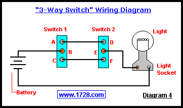 So, how does this work?
Let's say that Switch 1 is at the bottom
of a stairway and Switch 2 is at the top. Suppose Switch 1 is in a 'down'
position (B & C connected) and Switch 2 is in an 'up' position (D & E connected).
The light bulb is off. Now someone comes to the bottom of the stairs and
flips Switch 1 'up'. If you follow the circuit you can see why the light
bulb would now turn on because A & B and D & E are connected. When the person
reaches the top of the stairs, Switch 2 is flipped 'down', E & F are now
connected and so the light bulb goes off. Another person shows up at the
bottom of the stairs and flips Switch 1 'down', connecting B & C thereby
turning the light on again. The person reaches the top of the stairs, flips
Switch 2 'up' connecting D & E and the light bulb goes off. Notice that in
the case of the second person, a downstroke turns the bulb on and an
upstroke turns the bulb off. If you have such switches in your house OR if
you have purchased household wall switches for this circuit, you now see the
reason why they do NOT have the words on and off printed on them. So, how does this work?
Let's say that Switch 1 is at the bottom
of a stairway and Switch 2 is at the top. Suppose Switch 1 is in a 'down'
position (B & C connected) and Switch 2 is in an 'up' position (D & E connected).
The light bulb is off. Now someone comes to the bottom of the stairs and
flips Switch 1 'up'. If you follow the circuit you can see why the light
bulb would now turn on because A & B and D & E are connected. When the person
reaches the top of the stairs, Switch 2 is flipped 'down', E & F are now
connected and so the light bulb goes off. Another person shows up at the
bottom of the stairs and flips Switch 1 'down', connecting B & C thereby
turning the light on again. The person reaches the top of the stairs, flips
Switch 2 'up' connecting D & E and the light bulb goes off. Notice that in
the case of the second person, a downstroke turns the bulb on and an
upstroke turns the bulb off. If you have such switches in your house OR if
you have purchased household wall switches for this circuit, you now see the
reason why they do NOT have the words on and off printed on them.
Don't you think this switching arrangement
would make a great science project?
The Double Pole Double Throw Switch
A simple way to think of this switch is imagining
2 SPDT switches side by side with the 'handles' attached to each other.
Perhaps the most popular use for this switch is
'phase or polarity reversal'. So, how does the DPDT
switch accomplish this?
First, you have to wire the 2 'top' and 2 'bottom' terminals in a
'criss-cross' fashion. The top 2 terminals become the input and the middle
two terminals become the ouput. Now, referring to the bottom left diagram,
the switch is in the 'up' position, W & Y are connected, as are X & Z. The
polarity is maintained because the input and output are directly connected.
No problem seeing that right?
 Now let's see what happens when the
switch is in the 'down' position (right diagram). The + input goes from the
'W' terminal, down to the lower right and then up to the 'Z' terminal. The negative
input goes from the 'X' terminal and out through the 'Y' terminal. See what
has happened? With one flip of a switch, polarity has been reversed. What
applications does this have? For one thing, electric guitar players use this type
of switch to put one pickup out of phase with the other, producing a thin,
'squawcky', 'inside-out' kind of sound. In the 'old days' before 3 prong
plugs, power switches on some electrical devices used this switching
arrangement to switch polarity in case the plug was in the outlet the
"wrong way".
Now let's see what happens when the
switch is in the 'down' position (right diagram). The + input goes from the
'W' terminal, down to the lower right and then up to the 'Z' terminal. The negative
input goes from the 'X' terminal and out through the 'Y' terminal. See what
has happened? With one flip of a switch, polarity has been reversed. What
applications does this have? For one thing, electric guitar players use this type
of switch to put one pickup out of phase with the other, producing a thin,
'squawcky', 'inside-out' kind of sound. In the 'old days' before 3 prong
plugs, power switches on some electrical devices used this switching
arrangement to switch polarity in case the plug was in the outlet the
"wrong way".
Another important (though not very common)
use is to put this
switch between 3-way switches so that the same light may be switched from
many different locations. Referring to Diagram 4, if A & B and E & F were
connected, the bulb would be off. But now think of the wires going from A to D
and C to F. If their connections were reversed, ( A to F, C to D), the light bulb
would turn on again. So, how would we be able to reverse the polarity of these
2 wires? By using the polarity reversing switch ! (See Diagram 5 below).
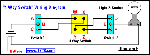 Incidentally, electricians have once again
stuck us with another misnomer by calling this a "4-way" switch. Can you see
what the 4-way switch is? It is a DPDT switch, wired for phase reversal
without the bottom 2 terminals exposed (they don't have to be). If you can
buy a 4-way switch, great. If not, you know how to make one right?
Incidentally, electricians have once again
stuck us with another misnomer by calling this a "4-way" switch. Can you see
what the 4-way switch is? It is a DPDT switch, wired for phase reversal
without the bottom 2 terminals exposed (they don't have to be). If you can
buy a 4-way switch, great. If not, you know how to make one right?
Also,you don't have to limit yourself to using just one 4-way switch. If you were to
attach a second 4-way switch from the Y and Z terminals of the first switch to the W2 and X2 terminals
of the second switch, you could have the same light switched from a 4th location. (See Diagram 6).
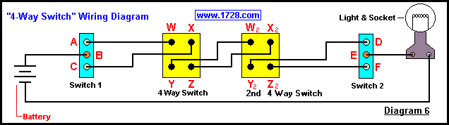 Or you could add a 5th or 6th switch, etc. Now wouldn't that make an impressive science project?
Good luck with the project !!!
Return To Home Page
Copyright © 1999 -
1728 Software Systems
|